SHANGHAI MICROCRE OPTICS-MECH TECH CO., LTDAbout MICROCRE400-812-7833
METHODS

Metal tensile testing: from force to stress–strain

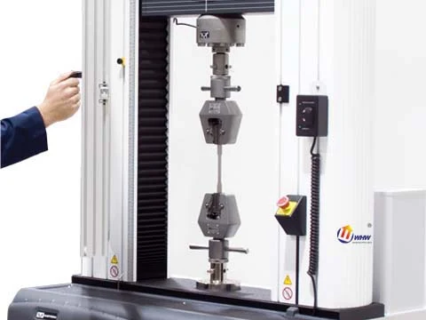
A tensile test applies axial force under defined conditions to determine strength and ductility. Valid results depend on specimen orientation, original cross-section, gauge length, alignment and strain measurement. Crosshead motion includes grip and frame deformation and cannot replace gauge-length extension without validation.

Theory & worked calculations

Item

Translation pending review.

金属拉伸:应力、应变与面积误差:模型与量纲

Equation

σ=F/A0;ε=ΔL/L0×100%

Variables & dimensions

Translation pending review.

F=10000 N;A0=20 mm²;L0=50 mm;ΔL=0.1 mm;误填面积=19 mm²

Assumptions & limits

Translation pending review.

假设载荷轴向且截面测量具有代表性。工程应力不等于颈缩后的真实局部应力;不利用该教学点推断材料牌号、合格与否或寿命。

Worked example

Translation pending review.

假设输入演算:10000/20 = 500 MPa;0.10/50×100 = 0.2 %;10000/19 = 526.315789 MPa。面积误填小5%使应力高约5.263%,并非恰好5%,因为面积位于分母。应变0.2%只描述当前几何变化,不等于已经测得Rp0.2。

Reporting requirements

Translation pending review.

以试样编号关联原始图像、测量序列、设备配置及方法版本。

Translation pending review.

分别报告重复性、异常处理及本模型未覆盖的影响因素,不用演算示例替代实测。

Common misconceptions

Translation pending review.

一个载荷点不能给出屈服强度或疲劳寿命;须保留完整曲线并按适用方法求取指标。

Translation pending review.

横梁位移包含试验机及夹具变形,不可未经验证当作标距内应变。

Workflow & steps

01

Sample and measure

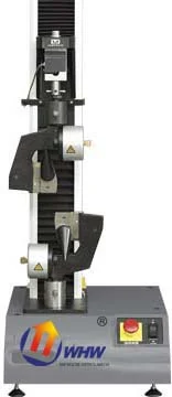
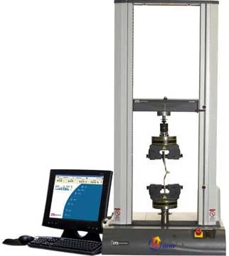
Select specimens from material, product form and the applicable standard, recording sampling position and orientation. Measure original cross-sectional area A0, gauge length L0 and key dimensions. Inspect machining quality and edge defects.
02

Select range and grips

Choose the load cell and grips for the expected force, checking force and extensometer calibration. Grips should transmit axial force without slipping or introducing bending. Match extensometer range and gauge length to the specimen.

03

Control rate and acquire data

Specify control mode, rate and transition conditions, recording time, force and gauge-length extension synchronously. Record test temperature and unusual events, distinguishing control requirements near yield from settings used later toward fracture.

04

Calculate and inspect curves

Engineering stress is σ=F/A0 and engineering strain ε=ΔL/L0. With F in N and A0 in mm², stress is in MPa. Determine yield or proof strength and tensile strength using the applicable procedure. Engineering and true stress curves are not interchangeable.

05

Measure after fracture and report

Measure gauge length or cross-section after fracture as required, checking whether fracture location affects validity. Save raw curves, dimensions, control settings and anomaly notes. Report scatter across repeat tests rather than retaining only one representative curve.

Checks

  • • Record material, dimensions, orientation, temperature and control rate.
  • • Ensure the extensometer's calibrated range covers the analysis interval.
  • • State definitions and calculation bases for yield, tensile and post-fracture properties.

Illustrative example

Teaching example: F=10,000 N and A0=20 mm² give 500 MPa engineering stress. L0=50 mm and ΔL=0.10 mm give strain 0.002, or 0.2%. These inputs do not establish the properties of any material.

Related instruments & resources

Links support navigation and do not establish a model’s performance or standards compliance.

Your next research question. Let’s explore.

Tell us about your material, specimen and measurement goal.

Discuss your application ↗
Find your instrument
⌕
Search products, cases, solutions, standards and literature.