
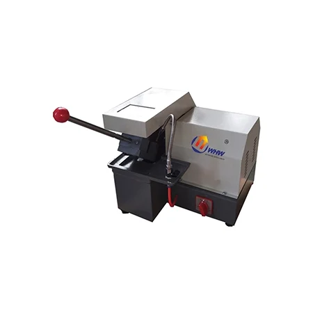
Material preparation
Q-2 · Metallographic cutting
Q-2


Explore the original technical specifications, related methods and configuration options. Chinese source specifications are retained for accuracy.
具有精确定位切割、多重定位连续切割、行程设定切割、在线调整进刀速度等各种功能;采用高强度机壳,双层可移动精密定位平台。分体式双平台双虎钳快速推进设计,利于各种不规则工件的加持。进刀行程任意设定,切割完毕自动停止并复位。切割速度1--200mm/分任意设定,并可根据切割情况随时进行在线调整;适用于一些大型工件、不规则件等各类工件的精密取样切割,尤其适合汽车零部件(如制动盘、减振器、各类大型轴杆及轴套、支撑架、、齿轮盘、异形件等)的取样。
| Parameter | Value / description |
|---|---|
| Model | ZQ-200 | ZQ-200A |
| Spindle speed | 100-3000r/min( no 极调速) | 100-3000r/min( no 极调速) |
| XPlatform / stageTravel | Manual70mm | Automatic70mm |
| Z-axis travel | 100mm |
| YPlatform / stageTravel | Automatic/manual(480mm) |
| YPlatform / stageAGI | 0-200mm( no 极调速) |
| Control system | 8寸彩色触摸屏、PLC控制系统(日本三菱) |
| Max. cutting size | 600X300X140mm |
| Cutting method | 手动/智能自动(双重模式) |
| Feed mode | Advance/retreat ratio freely settable |
| Effective feed travel | 400mm |
| Completion tracking | LCD digital display (continuous readout) |
| Cutting table size | 400X400mm |
| Cut-off wheel specification | (350-450)X(2-4)X32mm |
| Clamping table specification | Split-type double-layer movable stage |
| Cutting speed | 1-200mm/分钟 |
| On-the-fly speed adjustment | 任意调整 |
| Cutting feed distance | 任意设定(0-350mm) |
| Return mode | automatic reset |
| Cooling system | Automatic (water cooling, 4 channels) |
| Tank capacity | 200L |
| Motor power | 5.5KW-7.5KW(ABBMotor) |
| Machine configuration | Floor-standing integrated design |
| Power supply | 380V |
| Weight | 800-1000KG |
| Main unit | 1 unit |
| Y-direction moving stage | 1 set (on the main unit) |
| X/Y bidirectional positioning stage | 1 set (on the main unit) |
| Advancing clamp | Two pairs |
| Supplied tools | 1 set |
| Precision cutting blade | 两片 |
| Technical documents | One manual, one certificate of conformity, one warranty card |
| Optional: | Disc holder, rack holder, universal holder, longitudinal-section holder |
| Others: | Customizable fixtures for special workpieces |
| Automatic70mm | Z-axis travel |
Confirm the applicable method and standard.
Topic-based references do not certify this model or establish full conformity. Confirm the applicable edition, configuration and test conditions.
Scientific detail below is the Chinese source edition; reviewed full translations are pending.
Series-level guidance · Sample preparation · Confirm model capabilities, accessories and specifications.
A cut-off wheel or blade separates the specimen under controlled feed and cooling. The aim is to preserve the area for later observation and to limit cutting heat, deformation and edge chipping.
The schematic explains the basic mechanism; it is not a structural drawing of this model, an operating instruction or a measured result.
Controlled cutting and thermo-mechanical damage
Schematic model, not device footage or experimental data.
Follow inputs, actions, outputs and quality gates.
Define the research question: Can the cutting direction preserve the target defects and microstructure?; Can the cutting-damaged layer be removed in subsequent preparation? Record sample identity, target result and required configuration in the test plan.
Mark the sampling direction and allowance; check that the clamping position does not cover the target area.
Check cutting wheel/tool specifications, rated speed, cooling and protective interlocks.
Select blade, feed and cooling method according to material hardness and brittleness.
Cut after secure clamping; watch for overheating, vibration, edge chipping and jamming, and record the process.
Clean and label the cut face; check for heat tint, cracks and deformation, and plan the grinding allowance.
Archive the sample ID, model/accessories, raw records, processing version and anomaly handling with cross-references. Re-measure under identical conditions or check disputed results against the reference method.
Verify the edition, specimen and configuration. Links do not constitute certification or a conformity claim.
Such devices or accessories do not necessarily produce an independent measurand. First use the workflow below to confirm the calculation object, calibration basis and input units, then use the relevant reference tools.
Reference calculations ↗Links indicate related methods or research objects, not evidence that a paper used our instruments.
Standards index: Metallographic cutting, mounting, polishing and etching for Marine & offshore engineering. Organised ar…
Open research record ↗Testing solutions: Metallographic cutting, mounting, polishing and etching for General. Organised around GB/T 13298-2015…
Open research record ↗Industry applications: Metallographic cutting, mounting, polishing and etching for Semiconductor & packaging. Organised…
Open research record ↗Theory calculators: Metallographic cutting, mounting, polishing and etching for Marine & offshore engineering. Organised…
Open research record ↗Instrument principles: Metallographic cutting, mounting, polishing and etching for General. Organised around GB/T 13298-…
Open research record ↗Research workflows: Metallographic cutting, mounting, polishing and etching for Semiconductor & packaging. Organised aro…
Open research record ↗Other models in Metallographic cutting and the same instrument family.
Q-2
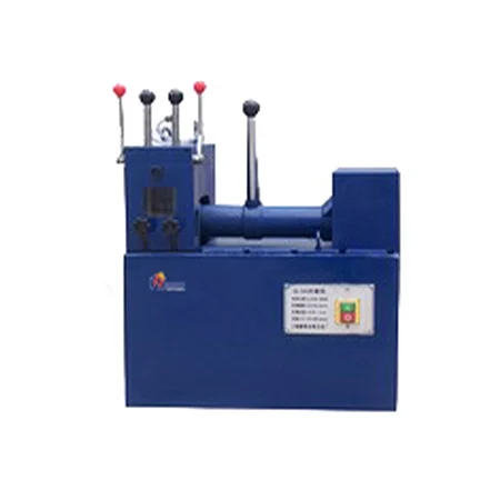
Q-3
Q-3A
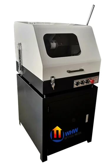
Q-4A

QG-1

QG-2
Tell us about your material, specimen and measurement goal.